 A 2018 publication by Sandia National Laboratories (SNL) [1] indicates that an overall more economical choice of wind turbine for an offshore floating turbine is a vertical axis wind turbine (VAWT). SNL has performed a comprehensive and extensive simulation study using a variety of software for different aspects, from stresses in blades to the levelised cost of energy (LCOE). There are several aspects involved in the design and operation of a wind turbine and even more if it is on a free platform subject to wave forces. In this study, the point of emphasis is the lower LCOE, as a result of smaller platforms for a VAWT, mainly due to the lower centre of gravity compared with a horizontal axis wind turbine (HAWT). This study and others on VAWTs point to the direction of the technology for floating turbines. After all, if the cost of energy is the principal driver for selecting a technology, then a lower LCOE is the preferred choice.
By Ahmad Hemami, McGill University, Montreal, Canada
While the remarkable work at SNL considers a Darrieus and a V-form turbine, it can be said that from several viewpoints the type of VAWT for the future must necessarily be one with pitchable blades. A Darrieus turbine has a few disadvantages, one of them being that the blades cannot be pitched. Also, from a manufacturing perspective, with regard to the already proven technology for straight blades, it is far behind. The same is true for transportation. For large turbines, which are expected for offshore, more likely the blades need to be made in segments.
Compared with the early days, wind turbine technology has made great progress. This progress has been exclusively for horizontal three-blade wind turbines. The VAWT was reasonably set aside long ago because of numerous drawbacks, among them starting difficulty, braking problems and lower energy capture capacity. It is important to note, however, that all these reasons go back to the technology and practice of some 40 years ago. We may see quite a different scenario if the progress in composite materials and pitching capability, which are practised for today’s turbines, are utilised for VAWTs of V-form or, preferably, U-form.
 The early designs had an H-form with fixed blades. A U-form VAWT with blade pitch capability can relatively easily make use of the already existing technology. The blades are straight, with the advantage of not needing a twist. This makes the scheme for operating speeds for variable speed functioning easier (all points on the blades have the same angle of attack). With blade pitch control, the turbine braking problem can be resolved. Also, today’s blades made of composite material are much lighter compared with those made long ago.
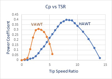
Considering the fact that for a variable speed turbine the operating speed can be selected such that the power coefficient (Cp) remains at its maximum value, as far as practicable, it is interesting to see the performance of a VAWT compared with a compatible HAWT. To do this relative comparison, the productivity of a typical HAWT compared with a VAWT of the same swept area, simple simulations for a 3MW turbine were carried out. For this purpose, the performance of the turbine in terms of Cp versus the tip speed ratio is required. This curve is not available for a turbine that does not exist and for existing turbines when manufacturers do not publish such data. Consequently, based on reasonable results, a conservative set of data for a HAWT and a VAWT, as shown in Figure 1, is used.
The simulations are for an average wind speed of 8m/s at the hub for a HAWT with 100-metre diameter. The cut-in and cut-out speeds are 3 and 24m/s, respectively. According to Figure 1, the best tip speed ratio is 8 (corresponding to Cp = 0.4). Accordingly, for wind speeds between 5 and 11m/s the turbine has a variable speed between 8 and 16rpm. For wind speeds smaller than 5m/s it rotates at 8rpm and for wind speeds larger than 11m/s it rotates at 16rpm.
For a U-form VAWT the aspect ratio (ratio between blade height and rotor radius) comes into effect. According to a 2014 article [2], a smaller aspect ratio results in a higher Cp. This fact has been implemented in the simulation only for setting the rotational speed and calculating the tip speed. As such, for a swept area the same as that of the HAWT, using a U-form turbine with 0.5 aspect ratio, the blade length is 62 metres and the radius 128 metres. Also, a tower height of 50 metres is considered, which leads to a 7.27m/s average wind speed based on the logarithmic model for the height effect.
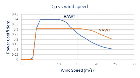
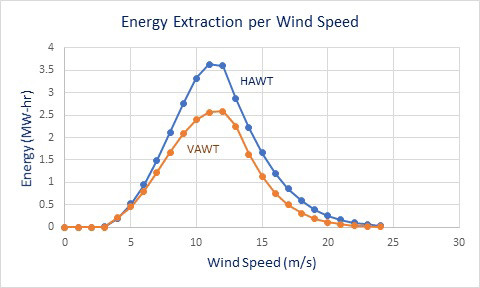 For the VAWT, the cut-in and cut-out speeds are 4 and 24m/s. It is assumed that the rotational speed increases linearly from 1 to 5rpm from the start to 15m/s wind speed and continues at 5rpm. Figure 2 illustrates the variation of Cp with wind speed for both HAWT and VAWT. The result of this comparison is shown in Figure 3, indicating the power grasp in MW for each wind speed. The average daily calculated power is 1.21MW for HAWT and 0.88MW for VAWT.
Further Reading
- Griffith, D.T. et al. 2018. Design Studies for Deep-Water Floating Offshore Vertical Axis Wind Turbines. Sandia National Laboratories Report SAND2018-7002.
- Brusca, S et. al. 2014. Design of a vertical-axis wind turbine: how the aspect ratio affects the turbine's performance. International Journal of Energy and Environmental Engineering 5(4):1-8.


